Background
(Skip this section if you're really only interested in the clock)
For
as long as I've been building things, I've felt very strongly that: "If
you can't draw it, you can't build it". I have a whole collection of
equipment to draw out my designs; from large sheets of graph paper, to
architectural rulers(Amazon),
compasses, and a plethora of other drafting tools. Designing is
ultimately a mental exercise, one that requires visualizing designs and
imagining how each piece interacts with another. Keeping all these
details in mind is an incredibly difficult thing to do well (Unless
you're Tesla himself, who was very proud of his ability to "perfectly" imagine mechanical designs). So I draw it out, and use it as a tool for design
instead of the design itself.
Before I start any project, I
make a few rough sketches to decide on exactly what I want - sometimes a
project will warrant scale drawings, (for which my architectural ruler
is invaluable). And sometimes it's a rough sketch illegible by any one
but me. Which brings up an important point - none of these sketches are
good. They're almost always drawn at right angles because I am not a
proficient sketch artist. Drawing at oblique angles and with perspective
would be pretty cool to help visualize it - but it is not necessary at
all.
As an example, here is a sketch I used to design a drum sander some time ago:


As
you can see, my preferred choice of graph paper is dotted as it doesn't
distract as much as the lines on regular graph paper does. My first
calculus professor taught me that blank sheets of paper are the best
choice for taking notes - especially math notes. I followed her advice
and never looked back. I still use blank sheets of paper when I need
something more free-form - but most often I need a little structure, and
dotted graph is the best compromise.
Over the past few months, I've been learning to use Fusion 360. A 3D modeling/CAD software. When 3D printing, or laser cutting materials, it's necessary to have a 3D model, or vector graphic to feed to the machine. So some sort of cad software is a requirement for building my own designs. This particular one has a fairly steep learning curve, and it requires certain level of rigor from designs (As in, it doesn't make it easy to rough sketch ideas, or quickly throw together models). But the level of detail and design it enables is incredible. I was able to design this whole clock before ever printing any thing. The physical parts only needed a little tweaking after they were printed. This is the largest project I've done yet with Fusion 360. So let's talk about the actual clock.
Finished
Design
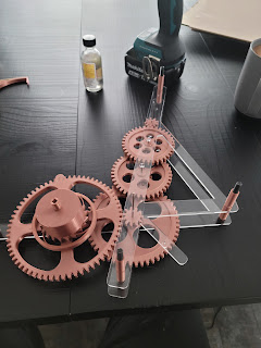
This
clock is a weight-driven pendulum clock. Like the classic Grandfather
clock. This is one of the simpler clock designs, as it's easier to build
than a spring-driven, or flywheel type clock. Notice the escapement at
the very top, and the drum for the weight on the far left. The gears are
attached to steel arbors, and mounted between laser cut sheets of
acrylic. The acrylic frame will be held together with 1/4" bolts passing
through 3D printed spacers/sleeves. The pendulum will be full size at
1m long, and the gears for the hour hand are such that one revolution of
the hand is 24 hours instead of the typical 12. I anticipate this clock
will be able to run for 5 days, but I'll need to run some tests with
the final build.


Escapement
The
escapement is the literal beating heart of a clock. It depends on
oscillations (In this case a pendulum) to advance the gears of a clock
at a specified interval of time (My clock is designed at once per
second). In a mechanical clock, it is the source of the ticking. This
device brought about a whole new way of keeping time, eventually leading
to the modern quartz crystal oscillator used in most modern clocks.
These crystals generate an
electrical signal at a specific frequency, and all digital devices use
these intermittent electrical pulses to to execute instructions.
There
are a number of different types of escapements, each with their own
advantages and disadvantages (You can read more about them here). I chose a deadbeat escapement, as it's a simpler design, but still very capable.

Escapements have two primary functions: To advance the gear train at a constant, known rate. And to power the oscillator (Pendulum, in this case). These two functions together is what makes an escapement such a marvel. As the pendulum swings, the pallet fork will rock back and forth. Each time allowing the wheel to advance one tooth. This is a 30 tooth wheel, and the pendulum will make a full swing once every 2 seconds. Meaning the escapement wheel will make a full rotation once per minute. I have attached a clock hand to the arbor of the escapement wheel - this is my second hand.
You'll
notice at the very ends of the pallet fork, there are angled faces that
directly contact the teeth of the escapement wheel. The escapement
wheel puts pressure on the fork, because it is being powered by the
weights through the gear train. As the fork rocks, and the escapement
wheel advances, the teeth will slide past these angled faces, causing
them to push on the fork just a little bit. Which in turn will push on
the pendulum. Left to it's own devices, a pendulum would eventually
stop, due to friction from the air, and pivot. But these angled faces
allow for the pendulum to be powered by the hanging weights.
With
the understanding that the escapement wheel turns once per minute, the
rest of the gear train was designed to convert once per minute, into
once per hour; to give us the minute hand.
Gear Train
The
gear train is the back bone of the clock. It includes the drum from
which the weights hang, as well as the gearing to convert from the per
minute rotation of the escapement, to the per hour rotation of the
minute hand. Some clocks will have multiple gear trains, as large
clocks with many complications might need multiple sources of power.
These complications might also need different gear ratios. An example
might be a day of the week complication, a moon phase complication, or
to display the orbits of the planets.

The wheel right in the
center with the four circles is the center wheel. This wheel rotates
once per hour. This means the gear ratio from the escapement to this
gear is 1:60. Starting from the escapement to the center wheel, my gear
teeth ratios are 9:36, 11:39, 13:55. You might wonder why I choose
such awkward ratios, and why not just have one pair of gears with a
teeth ratio of 8:480? It is very possible to create a clock like this -
but I did not want to have to create a wheel with 480 teeth. It would
have been huge, and likely beyond the capability of my 3d printer. Three
pairs of gears brought the size of each gear down to something much
more reasonable.
The seemingly random teeth ratios were chosen to
improve the longevity, and reduce the wear on each wheel. If you choose
a ratio that does not divide evenly (Eg. 36/9 is not an integer value,
but 36/12 is) you'll end up with different teeth meshing each rotation.
This allows the teeth to wear more evenly over the lifetime of the
clock.
Also notice that the sum of each meshing pair of wheels
increase monotonically - That is, 9 + 36 < 11 + 39 < 13:55. This
was important for my clock, because the gears overlap with each other,
and if the next pair of gears in the series were smaller than the
previous - the arbor would hit the previous large gear.
Hour Gear Train
The
hour gear train were probably the most difficult feature to design. They
are driven directly from the center wheel, and convert the once per hour
rotation, into once per 24 hour rotation.


The reason these were so tricky, is because in a typical clock the hour and minute hands are concentric with each other on the clock face. That meant I had to pick gear ratios such that the diameters of the gears allowed the input, and the output gear to also be concentric. The ratios that worked best for me were: 14:56, 10:60.

In the image to the left, you'll see the two concentric shafts for the hour and minute hands. The minute shaft comes from the center gear and connects to the input gear. And the hour shaft comes from the output gear.
The exact process I used to find these
gear ratios involved jiggling around a lot of factors, to satisfy these
two equations:
Find gear teeth ratios a:b, and c:d such that:
a + b = c + d
and
a / b * c / d = 1/24 (hours)
Instead of the painful process to find solutions to these equations, it's easiest to just run some code to find all solutions (gist)
54:15 60:9
54:18 64:8
56:14 60:10
60:9 54:15
60:10 56:14
64:8 54:18
30:10 32:8
32:8 30:10
32:12 36:8
Printing
For this iteration of the clock, I'm 3D printing all the gears, and laser cutting the acrylic frame. Here is the drum after printing:

Pile of printed gears:

Since the gears have steel arbors that need to fit tightly through the center, the gears need accurate holes. Printed plastic is well known to shrink 2% - 5% after cooling. This makes it difficult to get accurate holes. An easy solution is to print with the hole, and drill it out the rest of way.

It's important that you still print with the hole, even if you plant to drill it out. With default settings, holes are printed with walls. Theses walls provide some structure to the hole, and will guide the drill bit. Without these walls, the drill bit will tend to wander, especially so considering the infill might deflect the bit.

Assembly
The assembly was somewhat tricky. All the gears needed to be mounted on the arbors at specific points, so that they would mesh with the next gear in the train. I printed measured spacers so that I can easily, and quickly mount the gears at the right place before gluing to the arbor. Super glue worked really well for this.
Some of the holes were really tight, and difficult to push the arbors through. Using a drill to spin the arbor into place worked really well, and made mounting the gears really easy.

I test fit every thing, more than once. It's critically important to test fit before permanently gluing them. Here you can see I'm test fitting the gear train before attaching the hour train
The acrylic frame just had holes cut into it for the arbors to sit. To help retain them in the hole so they don't move around, I glued little acrylic dots on the outside of the frame, as seen in the following picture

Because my frame is clear acrylic, I wanted these glued dots to stay clear. I used this glue, and it worked really well, and kept the frame perfectly clear. It says it's for glass, but it worked fine with acrylic.

Double checking things fit nicely when it's set upright


No comments:
Post a Comment